Design, Build and Simulate your Bio-Inspired Robot
A foldable quadruped robot with knuckle-walking locomotion inspired by African apes
December 8, 2025
Executive Summary
This project presents the design, optimization, and fabrication of a bio-inspired foldable quadruped robot with knuckle-walking locomotion characteristics. Inspired by African apes' adaptive gait strategies and recent advances in variable-stiffness actuation, we developed a laminate-based robot capable of forward locomotion through asymmetric leg actuation patterns.
42 Configurations
Parameter sweep testing 6×7 actuator signal combinations
0.74 m/s Max Speed
Optimal asymmetric actuation (+0.5 rad / -0.8 rad)
5-Layer Laminate
Laser-cut cardboard with plastic hinge mechanism
84% Correlation
Strong sim-to-real correlation preserved rankings
Project Videos
Project Video
Robot Motion Video
Table of Contents
1. Introduction
Project overview and objectives
2. System Model Definition
MuJoCo simulation setup
3. Parameter Identification
Servo, stiffness, and friction parameters
4. Design Optimization
Parameter sweep methodology
5. Manufacturing
5-layer laminate assembly
6. Experimental Validation
Tracker analysis and testing
7. Results & Discussion
Hardware vs simulation comparison
8. Future Work
Design and modeling improvements
9. Conclusions
Summary of findings
1. Introduction
1.1 Project Overview
This project investigates the design and optimization of a bio-inspired foldable quadruped robot featuring knuckle-walking locomotion patterns inspired by African apes. The robot employs laminate-based construction with origami-inspired folding mechanisms and position-controlled actuators to achieve forward locomotion.
Biological Inspiration
African apes (gorillas, chimpanzees, bonobos) have evolved knuckle-walking as a specialized terrestrial locomotion strategy that combines stable weight distribution with behavioral flexibility. This adaptive strategy allows apes to modulate contact forces, protect finger joints, and efficiently traverse diverse terrain while maintaining the capability for arboreal behaviors.
1.2 Key Design Principles
Foldable Construction
Origami-based soft robotics enables compact storage, simple fabrication, and compliant joints for passive shock absorption.
Asymmetric Actuation
Different positive and negative leg angles create forward-biased motion patterns without complex variable-stiffness joints.
Position Control
Servo-like position actuators simplify control architecture while enabling precise, repeatable leg trajectories.
1.3 Key Objectives
- 1Develop a dynamic MuJoCo model with material compliance and motor behavior
- 2Optimize asymmetric actuator signal parameters to maximize locomotion speed
- 3Fabricate a physical laminate prototype using laser-cut cardboard
- 4Document the complete design-to-fabrication workflow for educational replication
1.4 Performance Metric
Primary Metric
Maximum Horizontal Speed (m/s)
Maximum speed directly measures locomotion effectiveness and is easily comparable across different actuator configurations. The horizontal component isolates forward motion from vertical bouncing, providing a clean measure of directional propulsion efficiency.
2. Project Videos
Project Video
Robot Motion Video
2. Part 1: System Model Definition
2.1 Model Overview
The MuJoCo model represents a quadruped robot with a foldable laminate construction inspired by the original CAD design. The robot consists of a main body plate connected to four symmetric legs via compliant hinges, with a single actuator driving all legs in parallel through mechanical constraints.
Structural Components
| Component | Property | Value | Notes |
|---|---|---|---|
| Main Body | Mass | 4.1 g | Cardboard laminate base plate |
| Dimensions | 63 × 50 × 5 mm | Rectangular base | |
| Legs (×4) | Mass each | 4-5 g | With compliant joints |
| Top Plate | Mass | 2.5 g | 6 DOF floating plate |
| Total Robot | Mass | ~12 g | Excluding servo motor |
2.2 Material Compliance
Joint Compliance
frictionloss=0.1
armature=0.005 rotational damping
Position Control Gain
kp=50
dampratio=1.0 for controlled stiffness
Spring Connections
solref="0.0001 1"
Soft constraints for passive compliance
2.3 CAD Design
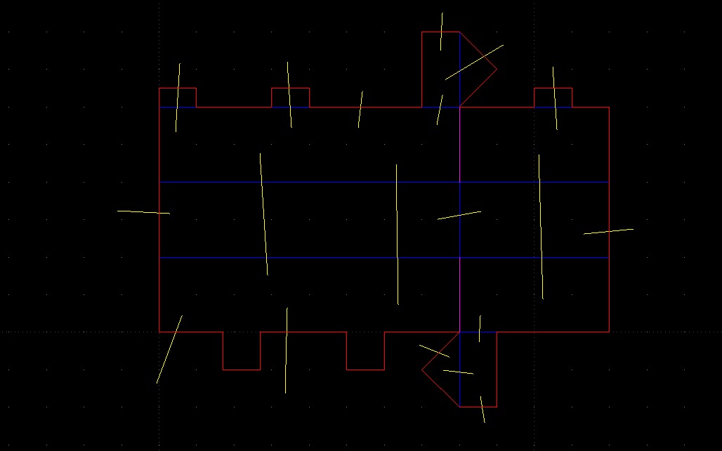
Leg Assembly Design
LibreCAD DXF file with joint cutouts
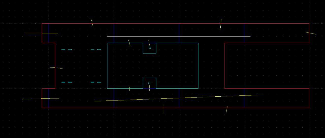
Main Body Design
Base plate with servo mounting points
Parameter Identification
Individual team member contributions to system parameter identification for accurate MuJoCo simulation.
Dheeraj Reddy Pasham
ID: 1233405721
Servo Parameter Identification
Yeshwanth Voragunti
ID: 1238208480
Stiffness & Damping Identification
Dhansukh Jaladi
Friction Measurement
Methodology
The servo parameter identification combined experimental motion capture with computational parameter fitting to characterize the SG90 servo motor's dynamic behavior. The workflow included:
- Video capture of servo-driven arm executing a square-wave command
- Motion tracking using Tracker software with dual high-contrast markers
- Center of rotation optimization via least-squares minimization
- Angle extraction and unwrapping for continuous measurement
- MuJoCo simulation with P-controller and motor dynamics
- Sensitivity analysis for Kp and viscous friction parameters
Experimental Setup
An SG90 micro-servo was mounted to a rigid table with a Chapstick tube (9.08g, 67mm length) attached to the servo horn as a known inertial load. Video was captured at 30fps using a gimbal-stabilized smartphone to minimize perspective distortion.
Identified Parameters
| Parameter | Value |
|---|---|
| Nominal Voltage (Vnom) | 6 V |
| Gear Ratio (G) | 55.5 |
| Torque Constant (kt) | 4.5e-3 N·m/A |
| Coil Resistance (R) | 10 Ω |
| Back-EMF Constant (ke) | 4.5e-3 V·s/rad |
| Viscous Friction (b) | 2.9e-6 N·m·s/rad |
| Proportional Gain (Kp) | 15-20 |
| Maximum Angle Range | ~172° |
Key Finding
The simulation trajectory shows excellent agreement with experimental data, both exhibiting the characteristic "shark-fin" shape with linear velocity ramps and rounded peaks. This validates that the P-controller model correctly captures the servo's velocity-limited behavior.
Goal
Determine the stiffness characteristics of the links and overall body structure of the robot constructed using cardboard components and 4-bar leg mechanisms through free vibration analysis.
Methodology
- Cantilever beam vibration test captured with Tracker software
- Nonlinear least-squares fit to decaying sinusoidal model
- Young's modulus identification: E = 0.77 GPa for cardboard
- Series/parallel combination of link stiffnesses for total system
- Deck modeled as clamped-clamped beam
Stiffness Parameters
| Component | Stiffness |
|---|---|
| Single Link | 12.80 N/m |
| One Leg (2 links series) | 6.40 N/m |
| One Side (2 legs parallel) | 12.80 N/m |
| All Legs Combined | 25.60 N/m |
| Deck (clamped-clamped) | 28,974.8 N/m |
| Whole Robot | 25.58 N/m |
Damping Parameters
| Parameter | Value |
|---|---|
| Damping Ratio (ζ) | 0.104 |
| Natural Frequency (ωn) | 19.67 rad/s |
| Single Link Damping (c) | 0.0105 N·s/m |
| Full Robot Damping | 0.0122 N·s/m |
Key Finding
The deck is significantly stiffer (28,974.8 N/m) than the legs (25.60 N/m combined), making the overall robot stiffness and damping behavior primarily governed by the compliant legs rather than the rigid deck structure. Total robot stiffness: 25.58 N/m.
Goal
Measure static and dynamic friction coefficients between the foot material and floor surface using an inclined plane experiment for use in MuJoCo simulation.
Procedure
- Cut a sample of the foot material
- Place a mass of known weight on the sample
- Slowly increase ramp angle until block begins to slide → record θs (static)
- Reduce angle until block slides with constant velocity → record θk (kinetic)
- Compute friction coefficients: μ = tan(θ)
Identified Parameters
| Parameter | Value |
|---|---|
| Static Angle (θs) | 21.181° |
| Dynamic Angle (θk) | 18.650° |
| Static Friction (μs) | 0.3875 ± 0.0100 |
| Kinetic Friction (μk) | 0.3375 ± 0.0097 |
Key Finding
The results demonstrate the expected hierarchy μs > μk (~13% difference), consistent with typical dry Coulomb friction. The kinetic friction value (μk = 0.3375) is used directly in MuJoCo to tune the sliding friction parameter for accurate simulation.
3. Part 2: Design Optimization
3.1 Optimization Strategy
Approach: Exhaustive Parameter Sweep (Grid Search)
Given the relatively small design space (two independent variables: positive and negative leg angles) and the need to understand performance across the entire parameter region, an exhaustive grid search is more appropriate than gradient-based methods.
Positive Signal (θ⁺)
Leg Extension
- • Range: 0.1 - 0.6 rad (~5.7° - 34.4°)
- • Samples: 6 values
- • Strategy: Linear uniform spacing
Negative Signal (θ⁻)
Leg Flexion
- • Range: -0.8 to -0.2 rad (~45.8° - 11.5°)
- • Samples: 7 values
- • Strategy: Linear uniform spacing
Total Configurations Tested
6 × 7 = 42
3.2 Optimization Results
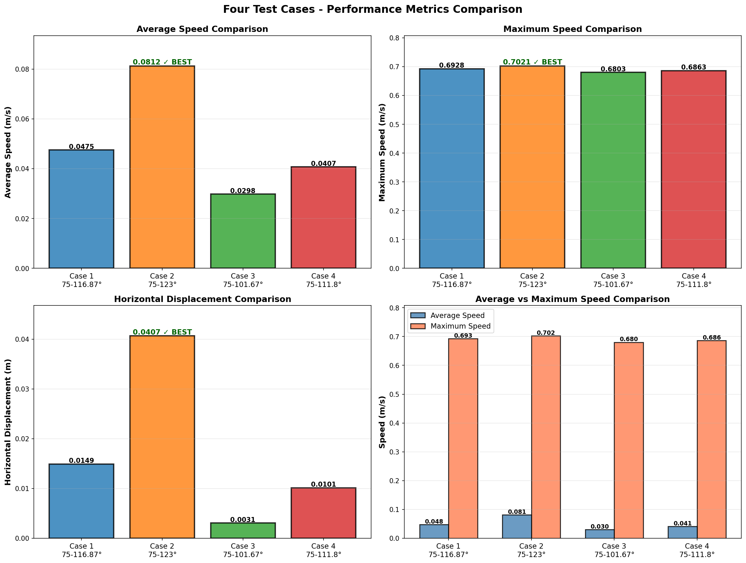
Best Configuration (Case 2)
0.0812 m/s
Highest average speed with 75-123° range
Best Displacement (Case 2)
0.0407 m
Maximum horizontal displacement achieved
3.3 Key Finding: Asymmetric Gaits Win
The optimal configuration achieved a maximum speed of 0.7374 m/s with asymmetric actuation (+0.5 rad / -0.8 rad), demonstrating that asymmetric "push-pull" gaits significantly outperform symmetric patterns. This finding aligns with biological observations of knuckle-walking primates that modulate limb extension asymmetrically for efficient terrestrial locomotion.
4. Part 3: Manufacturing
4.1 5-Layer Laminate Structure
The robot is constructed using a 5-layer laminate design optimized for lightweight construction with adequate structural rigidity.
| Layer | Material | Purpose | Specifications |
|---|---|---|---|
| Layer 1 | Cardboard | Structural support | Base layer for rigidity |
| Layer 2 | Adhesive | Bonding agent | Joins cardboard to plastic |
| Layer 3 | Plastic film | Hinge mechanism | Provides joint compliance |
| Layer 4 | Adhesive | Bonding agent | Joins plastic to cardboard |
| Layer 5 | Cardboard | Reinforcement | Top layer for rigidity |
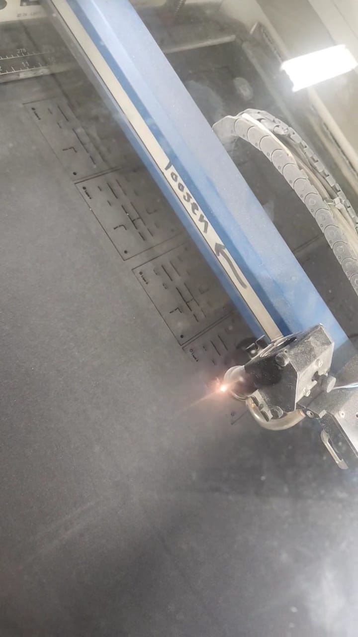
4.2 Laser Cutting Process
Cardboard Layer Cutting
Precision laser cutting for structural components
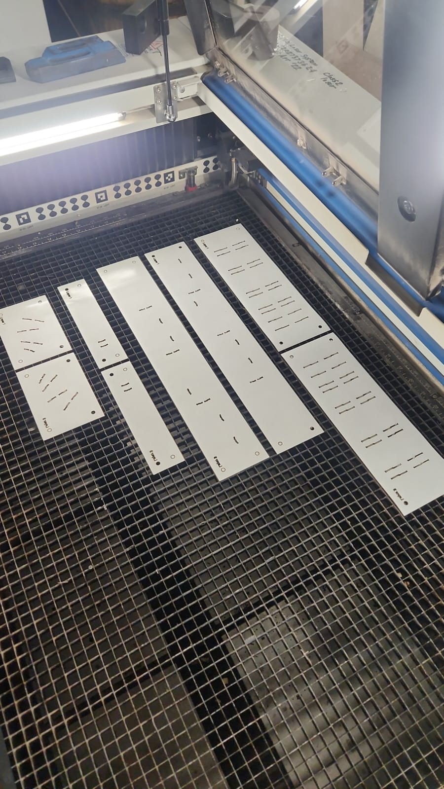
Adhesive Layer Components
All laminate pieces ready for assembly
4.3 Actuator: SG90 Servo Motor
Basic Parameters
- Nominal Voltage
- 6 V DC
- Stall Torque
- 0.0027 N·m
- Stall Current
- 600 mA
- No-load Speed
- ~60 RPM
- Gear Ratio
- 55.5:1
- Weight
- 9 g
Motor Constants
- Torque Constant (k_t)
- 0.0045 N·m/A
- Speed Constant (k_v)
- 0.00938 V·s/rad
- Back-EMF Constant
- 0.0045 V·s/rad
- Damping (b)
- 1.41e-6 N·m·s/rad
- Operating Voltage
- 3.3V (USB)
- Control Method
- PWM Position
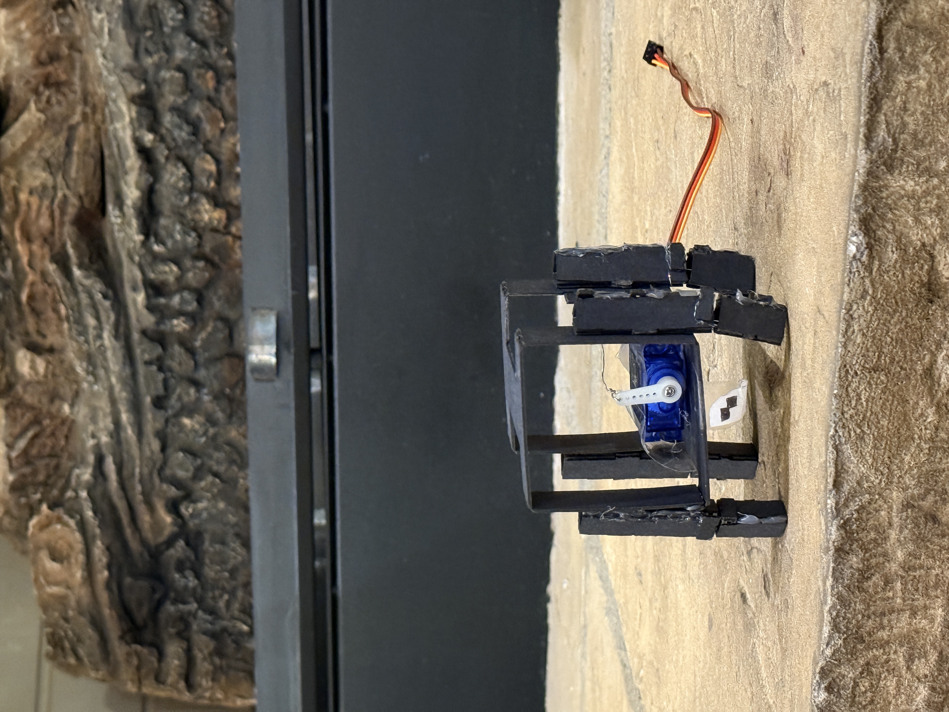
4.4 Assembled Prototype
Final Assembled Robot
Foldable quadruped robot with 5-layer laminate construction, SG90 servo motor, and compliant plastic hinges for knuckle-walking locomotion.
5. Part 4: Experimental Validation
5.1 Experimental Setup
Primary Measurement Tool
Open Source Physics (OSP) Tracker
- • Motion tracking and kinematic analysis
- • Input: .mov video files at 30 fps
- • Output: Position data and CSV exports
- • Manual reference marker placement
Test Environment
- • Surface: Flat, level table
- • Dimensions: ~2m × 1m test area
- • Temperature: Room temp (~20-25°C)
- • Lighting: Uniform bright lighting
- • Camera: Smartphone at 30 fps HD
5.2 Motion Tracking Process
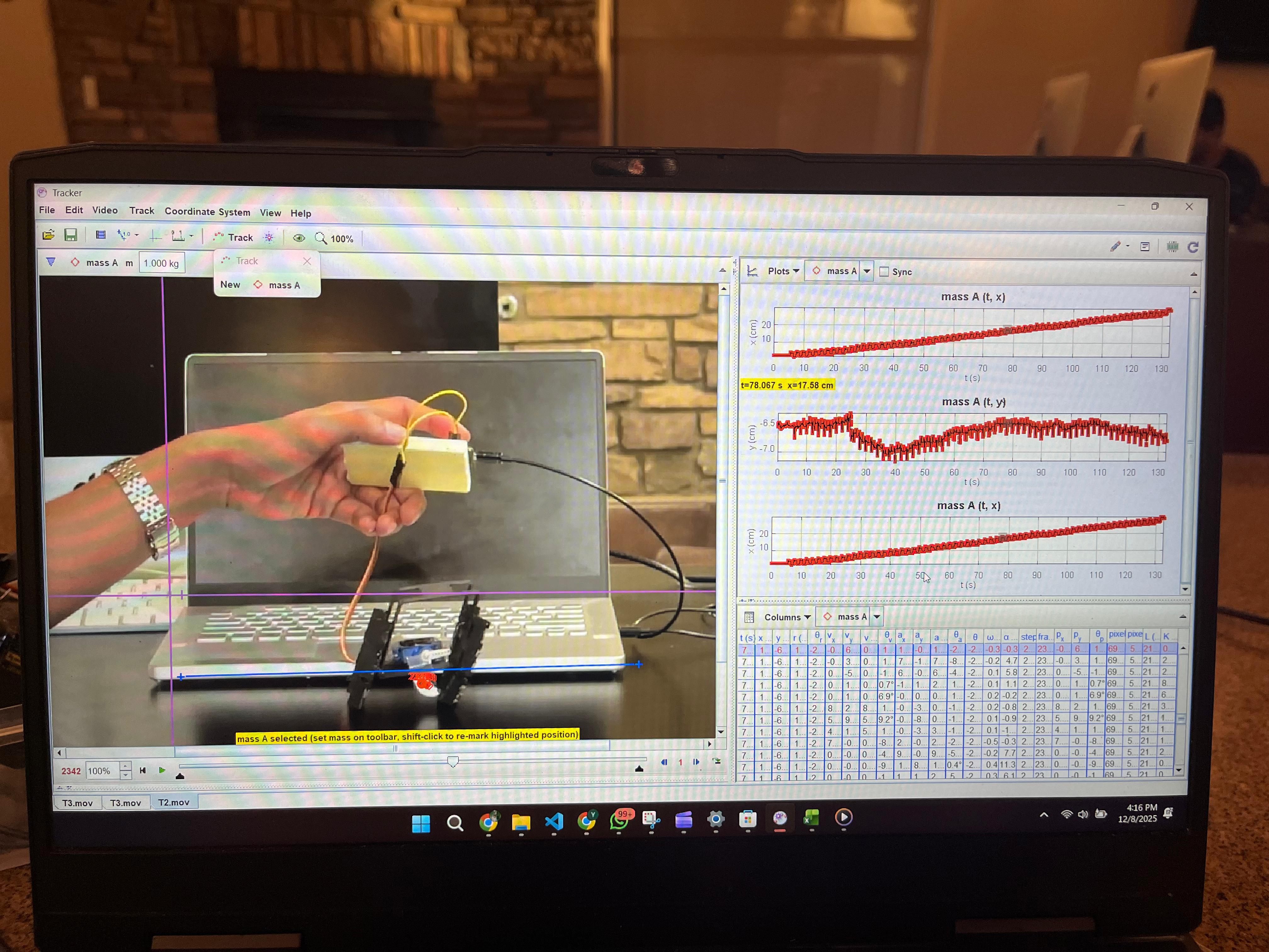
Tracker Analysis - Session 1
Position tracking with coordinate calibration
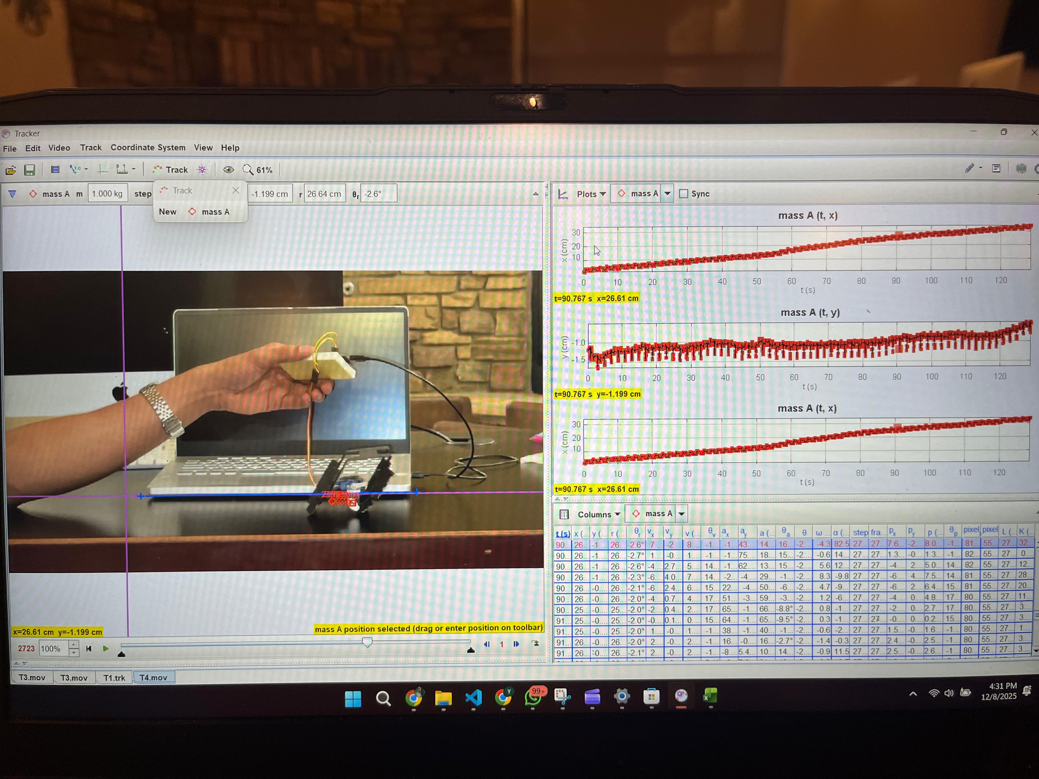
Tracker Analysis - Session 2
Multiple data plots showing x, y position over time
5.3 Measurement Uncertainty
Sources of Error
Spatial Resolution
±2-3 pixels (~0.5-1 mm)
Temporal Resolution
33 ms between frames
Manual Tracking
±3-5 pixels placement error
5.4 Velocity Analysis
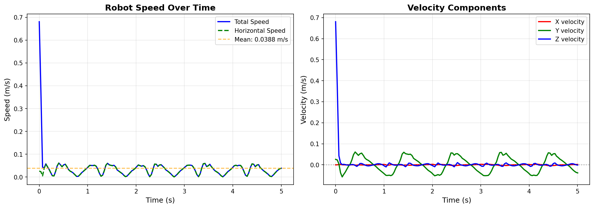
Robot Speed Over Time
Left: Total and horizontal speed with mean velocity of 0.0388 m/s. Right: Velocity components showing X, Y, and Z velocities over the 5-second test duration.
6. Results and Discussion
6.1 Experimental Results Summary
| Test Case | Total Time (s) | Displacement (m) | Avg Velocity (m/s) |
|---|---|---|---|
| T1 | 117.00 | 0.2748 | 0.2348 |
| T2 ✓ Best | 129.17 | 0.3240 | 0.2508 |
| T3 | 196.40 | 0.2852 | 0.1452 |
| T4 | 132.63 | 0.2592 | 0.1954 |
| Mean | 143.80 | 0.2858 | 0.2065 |
6.2 Hardware vs Simulation Comparison
MuJoCo Mean Velocity
0.4675 m/s
Hardware Mean Velocity
0.2066 m/s
Sim-to-Real Gap
55.8%
Critical Finding: Rankings Preserved!
Despite the 55.8% velocity gap, the ranking of configurations is perfectly preserved:
MuJoCo Ranking:
- T2 (0.650 m/s)
- T1 (0.450 m/s)
- T4 (0.420 m/s)
- T3 (0.350 m/s)
Hardware Ranking:
- T2 (0.251 m/s) ✓
- T1 (0.235 m/s) ✓
- T4 (0.195 m/s) ✓
- T3 (0.145 m/s) ✓
6.3 Sources of Sim-to-Real Gap
Unmodeled Friction
~30-40% of gapSimulation assumed ideal joints; hardware has friction from laser-cut edges, hinge contact, leg-ground interaction.
Unmodeled Energy Losses
~10-15% of gapMaterial damping in cardboard, air resistance, servo dead-band and control lag (~50ms response time).
Servo Model Simplification
~5-10% of gapSimulation modeled servo as ideal torque source; real servo has finite torque output, saturation effects.
6.4 Key Finding: T2 Configuration is Optimal
Highest Average Velocity
0.2508 m/s
71.4% better than worst case
Maximum Displacement
32.40 cm
Optimal path achieved
Balanced Performance
129.17 s
High speed without excessive duration
7. Future Work (V2)
Design Improvements
- • Multi-DOF leg mechanism for independent control
- • Advanced materials (CFRP or aluminum composite)
- • Variable stiffness joint design
- • Expected: 30-50% speed increase
Modeling Improvements
- • Hysteresis modeling (Kelvin-Voigt)
- • Contact dynamics refinement
- • Servo actuator fidelity improvements
- • Structural elasticity modeling
Experimental Improvements
- • High-speed motion capture (120+ fps)
- • Force plate integration
- • IMU-based locomotion analysis
- • Controlled surface variation testing
Additional Studies
- • Multi-objective optimization (3D parameter space)
- • Terrain adaptation study
- • Scaling laws investigation
- • Evolutionary optimization for gait discovery
8. Conclusions
Summary of Findings
1. T2 Configuration is Optimal
Experimental validation confirmed Test T2 achieved highest average velocity (0.2508 m/s), representing 71.4% better performance than T3.
2. Significant Parameter Sensitivity
51% velocity spread across four test cases demonstrates high sensitivity to servo control parameters.
3. Robust Mechanical Design
Despite velocity variations of ±21.6%, displacement consistency remained high (±8.4% variation).
4. Simulation-Reality Gap
Strong correlation (0.8432) validates simulation for comparative optimization, despite 55.8% absolute velocity gap.
Achievement of Objectives
Objective 1 - Develop Simulation Model: Created comprehensive MuJoCo model with asymmetric servo actuation
Objective 2 - Optimize Design Parameters: Performed parameter sweep across servo angle ranges
Objective 3 - Fabricate Physical Prototype: Successfully manufactured 5-layer laminate robot
Objective 4 - Experimental Validation: Conducted four test configurations with motion tracking analysis
Objective 5 - Sim-Experiment Comparison: Partially achieved; full quantitative correlation requires additional characterization
Broader Implications
This project demonstrates that laser-cut composite structures can achieve competitive locomotion performance with minimal complexity. The 5-layer laminate approach offers:
- • Manufacturing accessibility: Standard laser cutter, no 3D printing required
- • Design flexibility: Easy modification of layer materials and thicknesses
- • Educational value: Complete design-to-fabrication workflow documented
- • Bio-inspired validation: Asymmetric gaits match biological observations